

“Bremar Automotion’s simulations helped us reduce mass without compromising on safety. We could not be happier with their professionalism and technical knowledge.”
OUR EXPERTISE
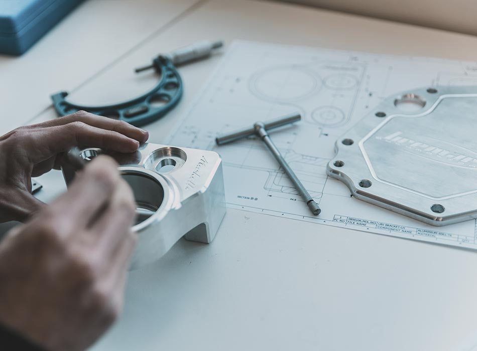
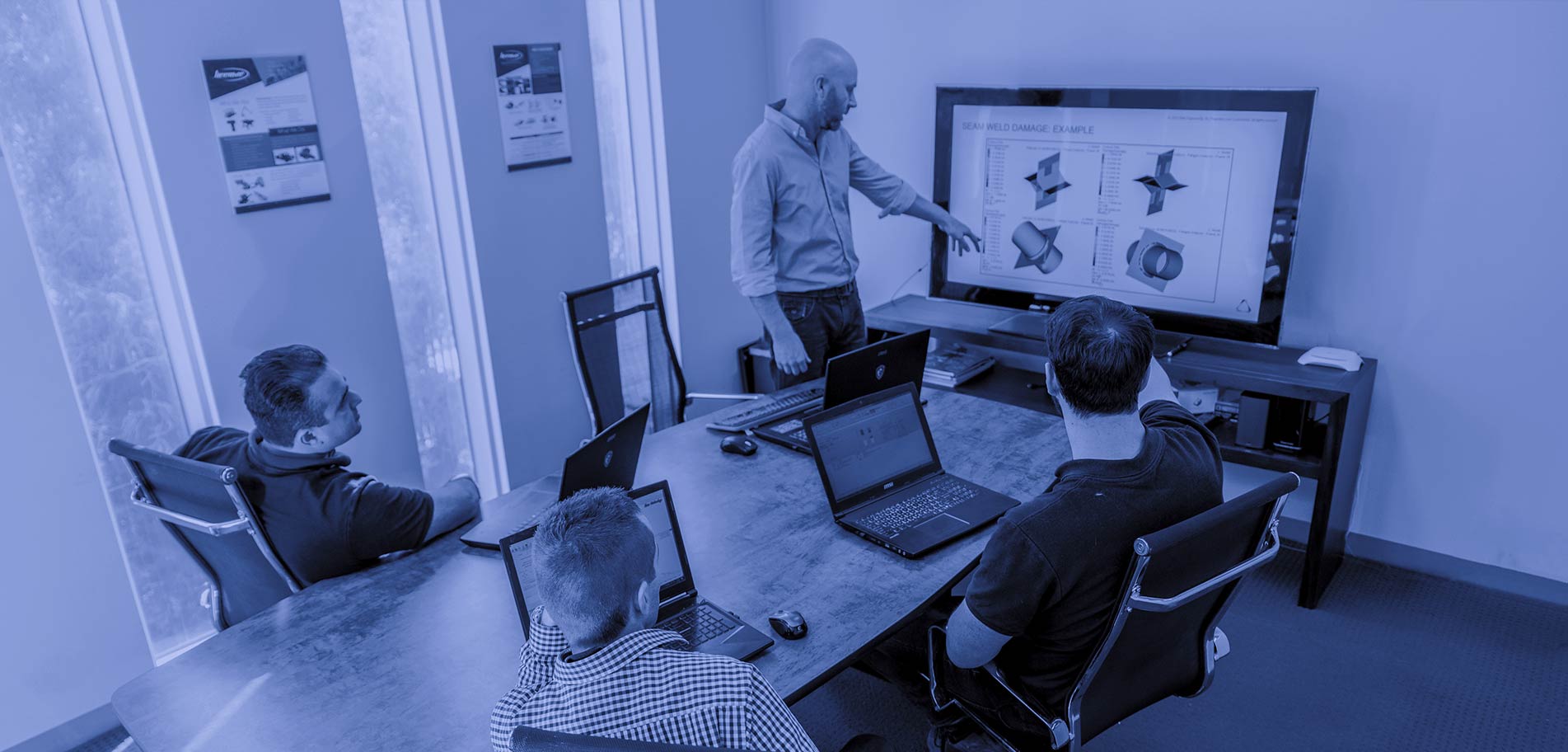
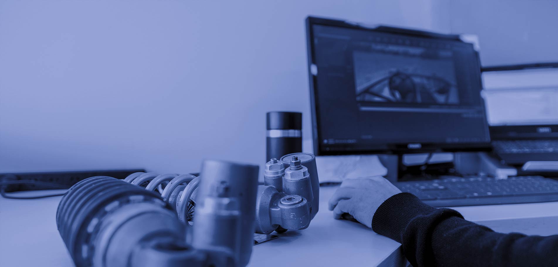
We are passionate about providing world-class engineering analysis to small and medium sized businesses who can't justify the cost of in-house engineering capabilities, and consulting to larger companies to provide expert knowledge and tailored engineering solutions.
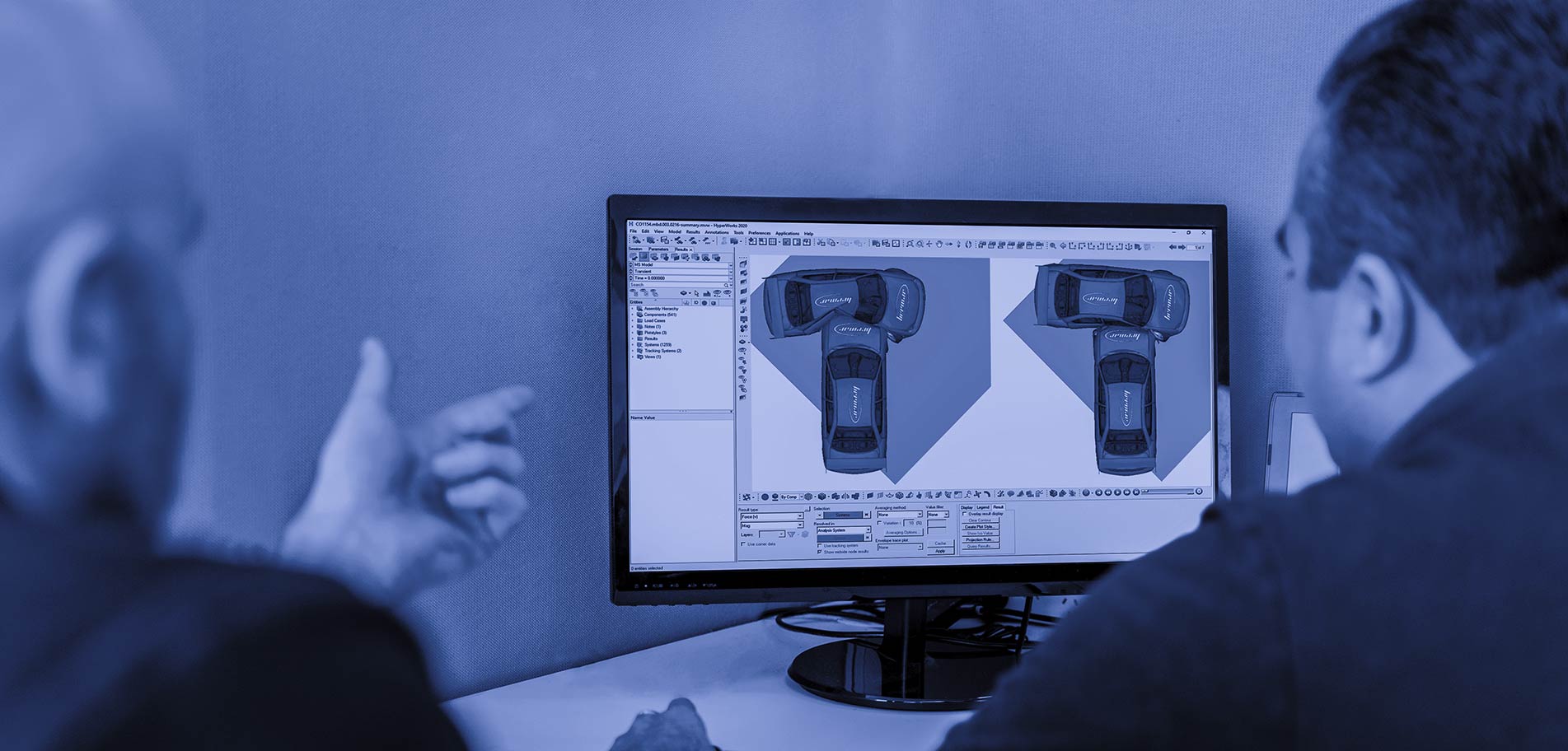
Using the same simulation software as industry leading companies like Ford, GM and Boeing, our passionate, hands on engineers bring over 40 years’ combined engineering experience from the national and global stage.
Significantly improve every step of your product development cycle, creating optimised products faster and more efficiently while significantly reducing costs.
• Low Volume, Niche & OEM Automotive • Motorsport • 4x4 & Off-road • Trailer & Caravan • Mining Equipment • Heavy Vehicle • General Engineering
WHAT'S HAPPENING TODAY AT BREMAR AUTOMOTION AS SEEN ON INSTAGRAM
WHAT OUR CLIENTS ARE SAYING
“We have found their attention to detail, consideration of ‘how to manufacture’ and problem solving very good and can highly recommend their services.”
“We have always found each of their friendly staff easy to work with while remaining very professional. Our business relationship has prospered through common paths in Automotive Engineering and we look forward to that continuing.”
“We have used Bremar for many years for FEA simulations on automotive, heavy vehicle and general engineering projects, and I would highly recommend using their services”